
Intro
I’ve long held a love for jailbreaking video game consoles. In years prior, I’ve jailbroken PSPs, 3DSes, PS3s, Wiis, and more. However, I’ve only once done a successful hard-mod of a console, my Nintendo Switch. The only other time I tried to hard-mod a console, an Xbox 360, I fried the thing. Given that I’ve been trying to get better at soldering lately and my roommate had a GameCube and four (!!!) controllers, I figured that it would be a good candidate to mod!
Ordering Parts
I figured there’d be two main things I’d need for this project: a Raspberry Pi Pico and some way to connect an SD card to the console. Thus, I went on eBay and purchased a Pico and an SD2SP2. My rationale behind ordering the Pico off of eBay was that I didn’t have a Micro Center near by to purchase at MSRP and the rationale behind the SD2SP2 was that it was probably going to be the best fit for my roommate’s DOL-001 console. I didn’t purchase anything in the way of supplies as I already had a soldering iron, flux, and solder. The guide called for thinner gauge wire than what I had, but what’s the worst that could happen?
The First Mistake
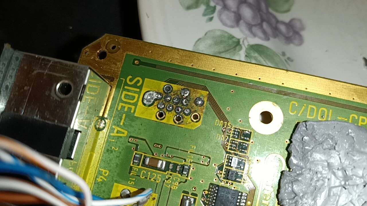
20 minutes later, I thought, “Huh, I should have actually checked that the GameCube has an SP2 port”. I take off the cover and lo and behold, it doesn’t. Turns out, the port is present on most DOL-001 consoles, but not all. I did some research after this discovery and found that this wouldn’t be a huge problem. Turns out the board still has the points for the SP2 socket, they’re just not populated. With more digging, I found that 0ctobogs1 on GBATemp had installed an SD2SP2 internally and only needed to add a single blob of solder to a point labeled FIL22 on the bottom of the board2. I figured I’d take the capacitor that comes on the SD2SP2 board and create the adapter outlined by wolffangalchemist3 in the thread I found this comment on4
The First Attempt
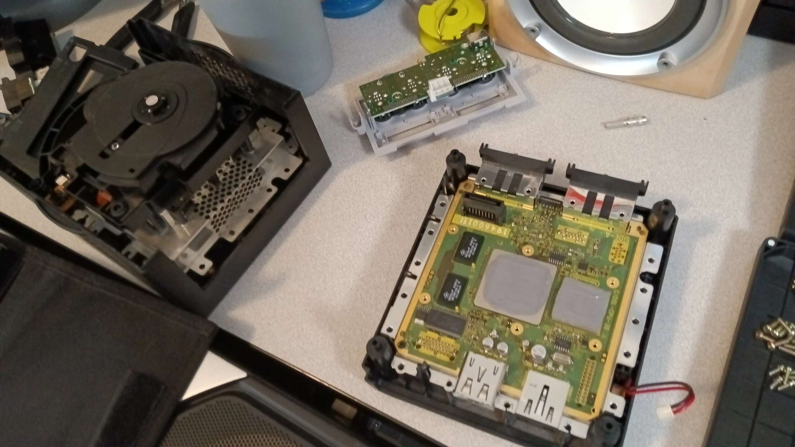
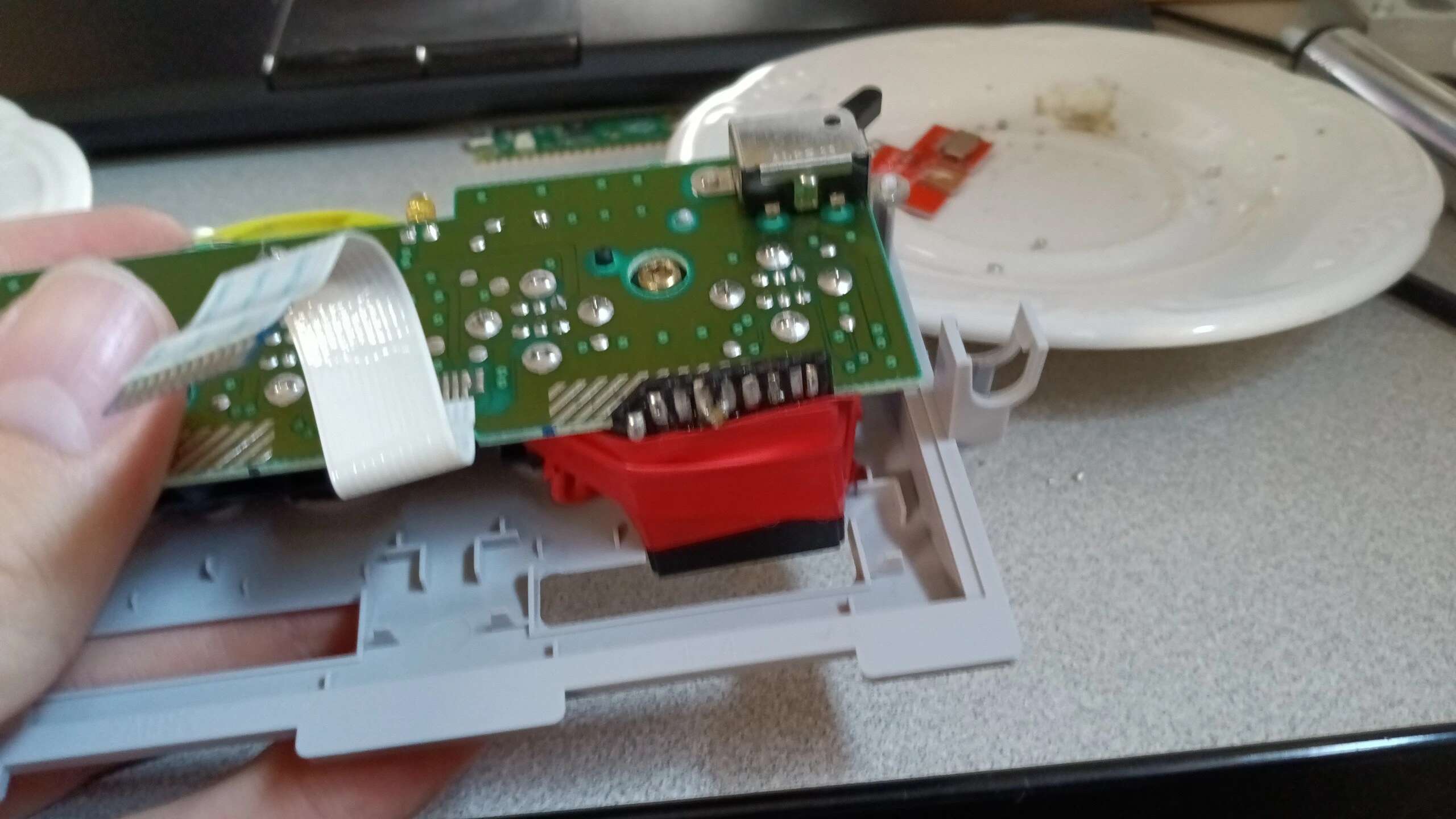
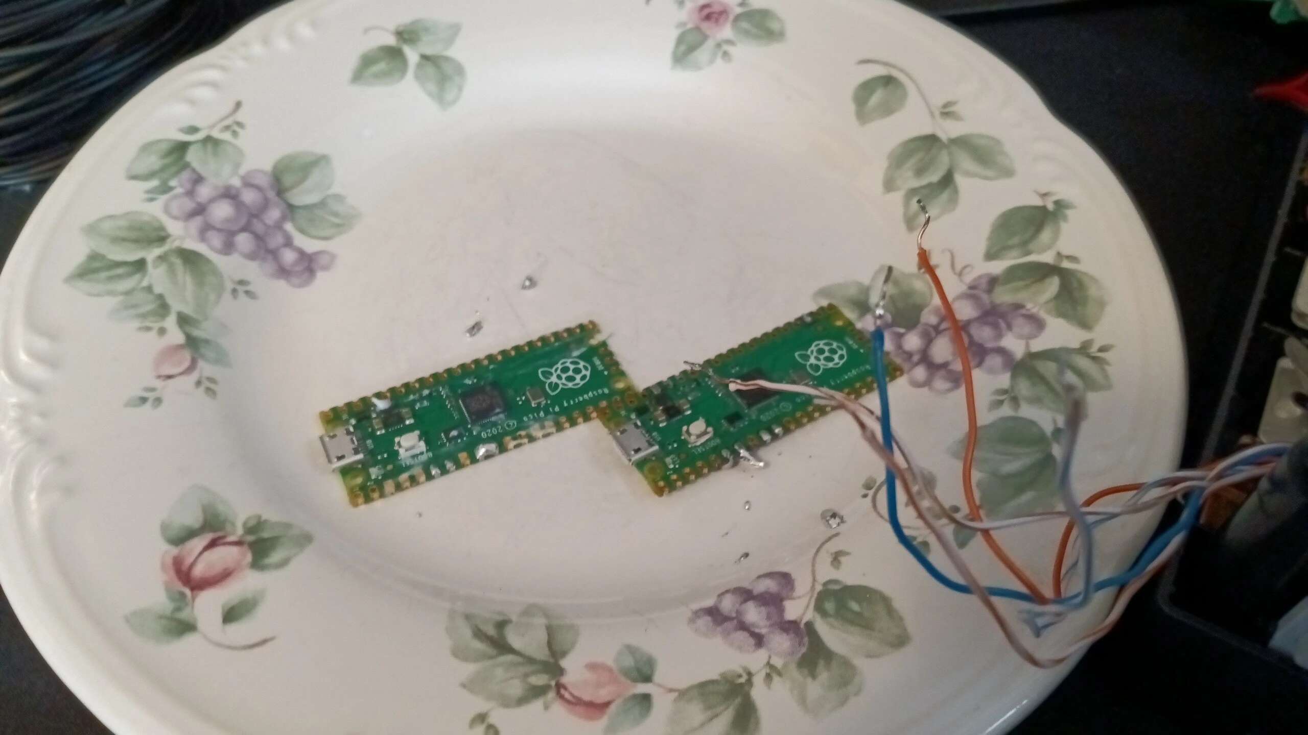
Once the packages arrived, I heated up the soldering iron and got to work. First thing I did was prepping the SD card and the Pico. This was no hassle as it was mostly copying files around. Taking apart the console was also no problem. Since my roommate had kept it in good condition, there was no grime or gross stuff to clean up on the way in.
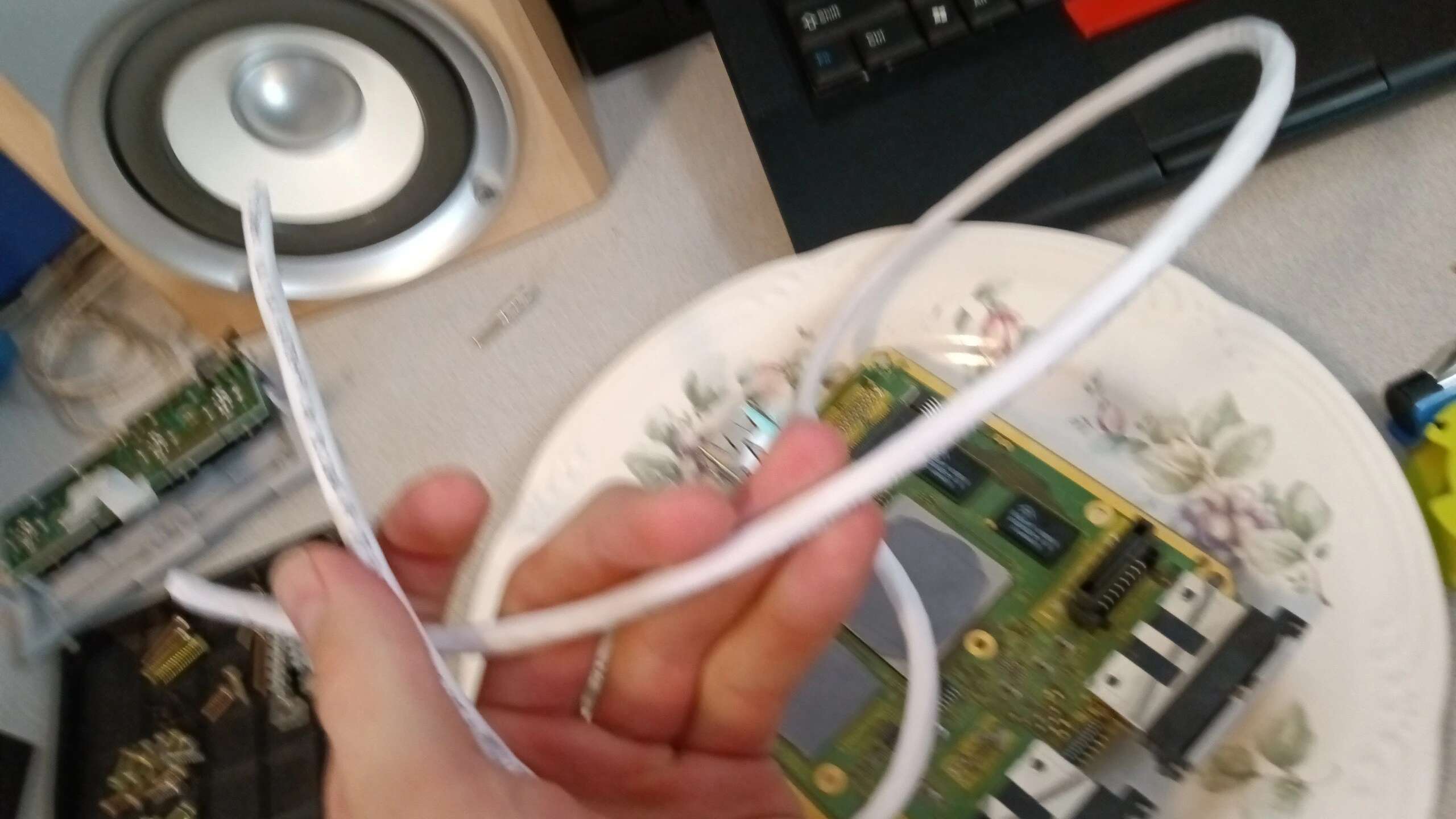
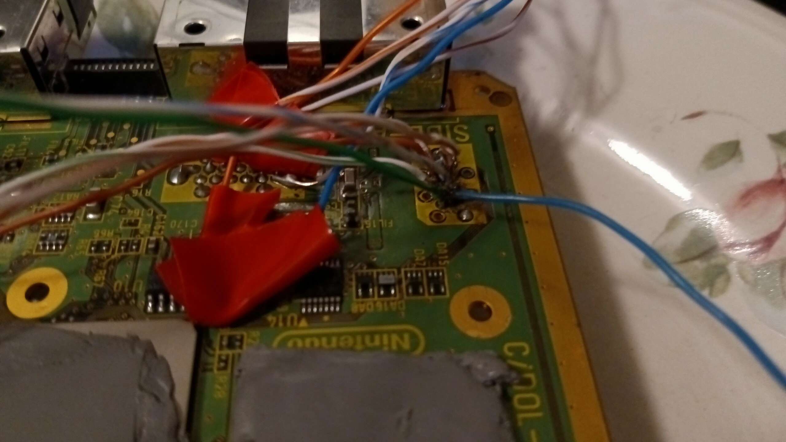
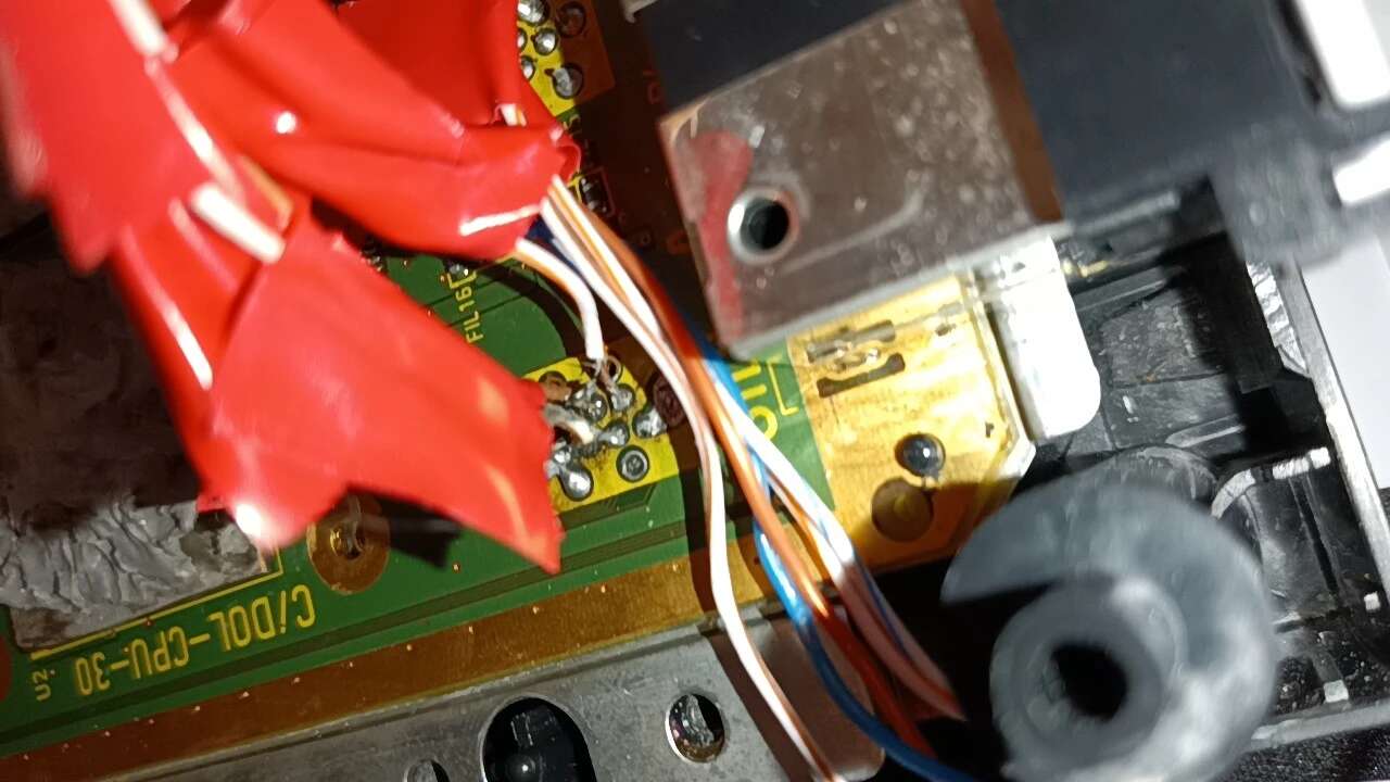
When selecting the wires I wanted to use, I initially thought I’d use an older CAT5 cable I had lying around. Unfortunately, I found it difficult to get the wires in this cable to tin up. I ended up using some thicker CAT6 cabling I had bought in bulk.
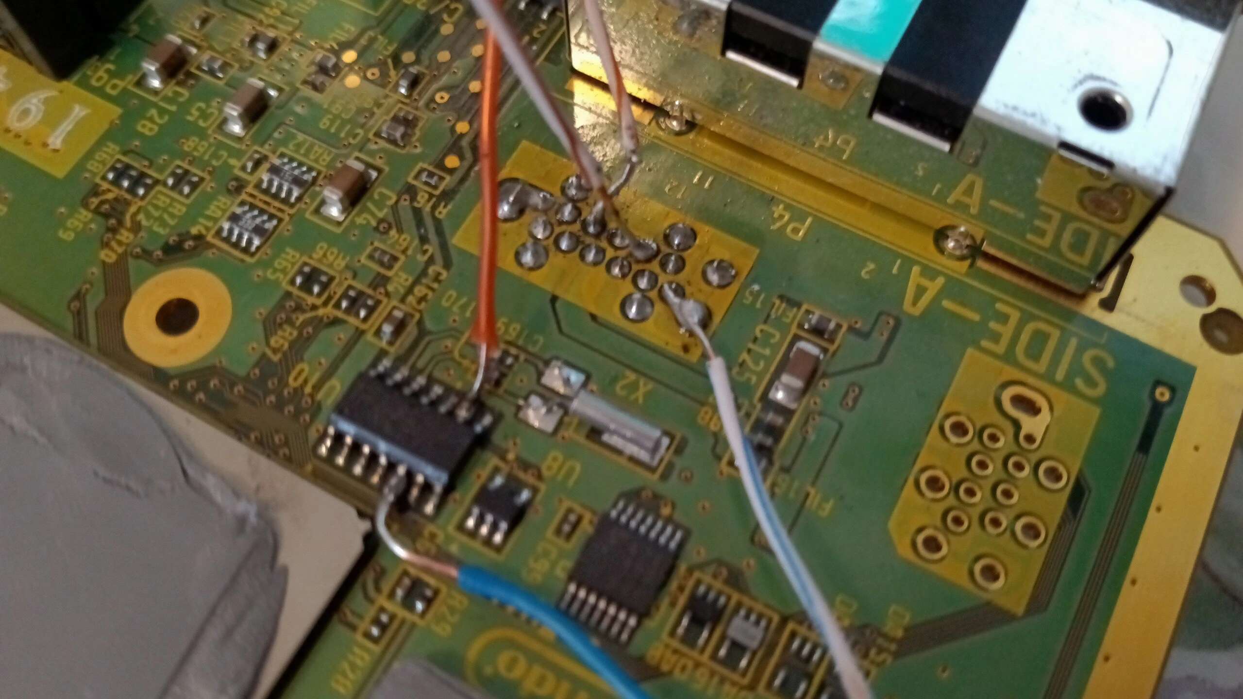
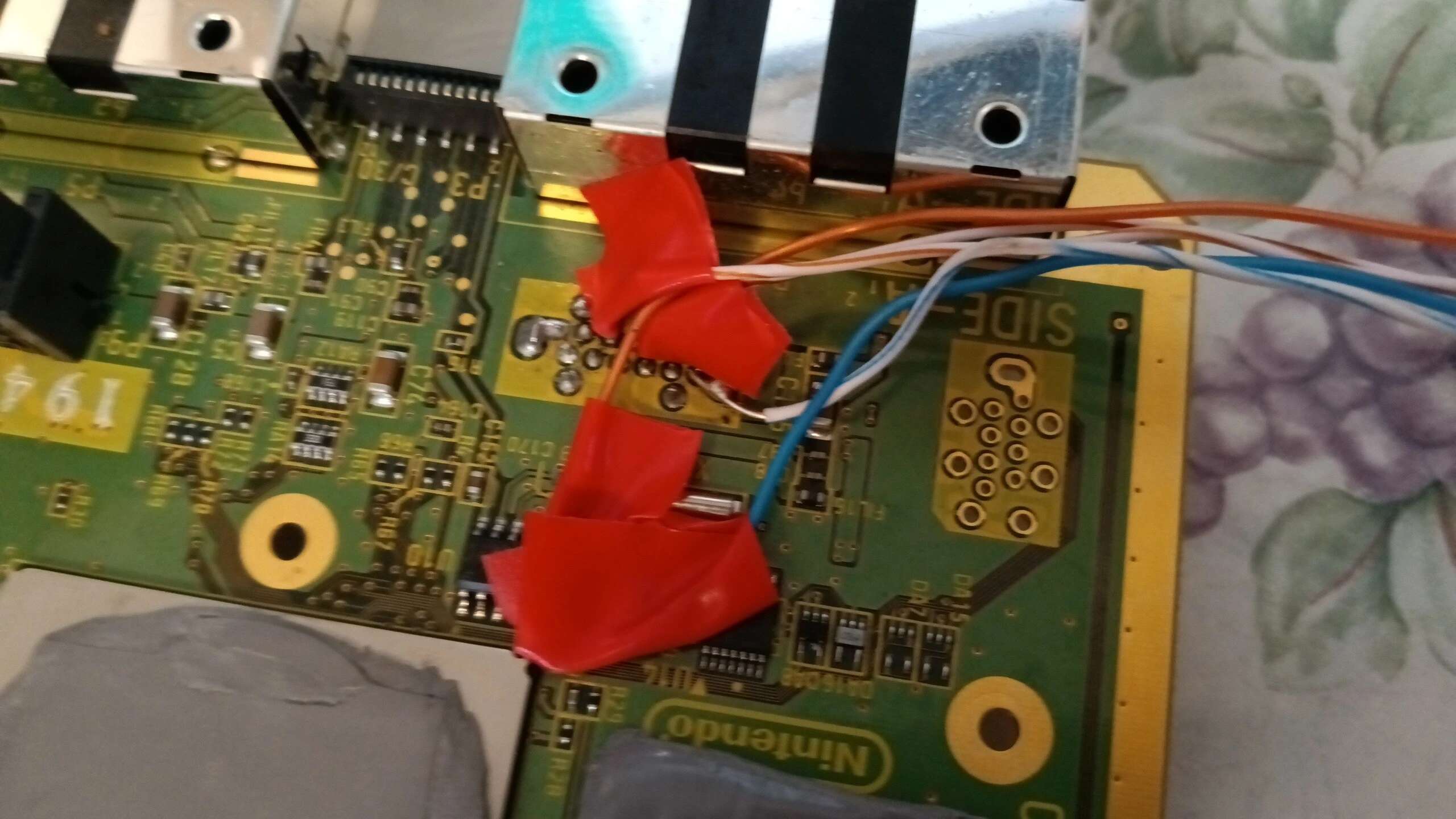
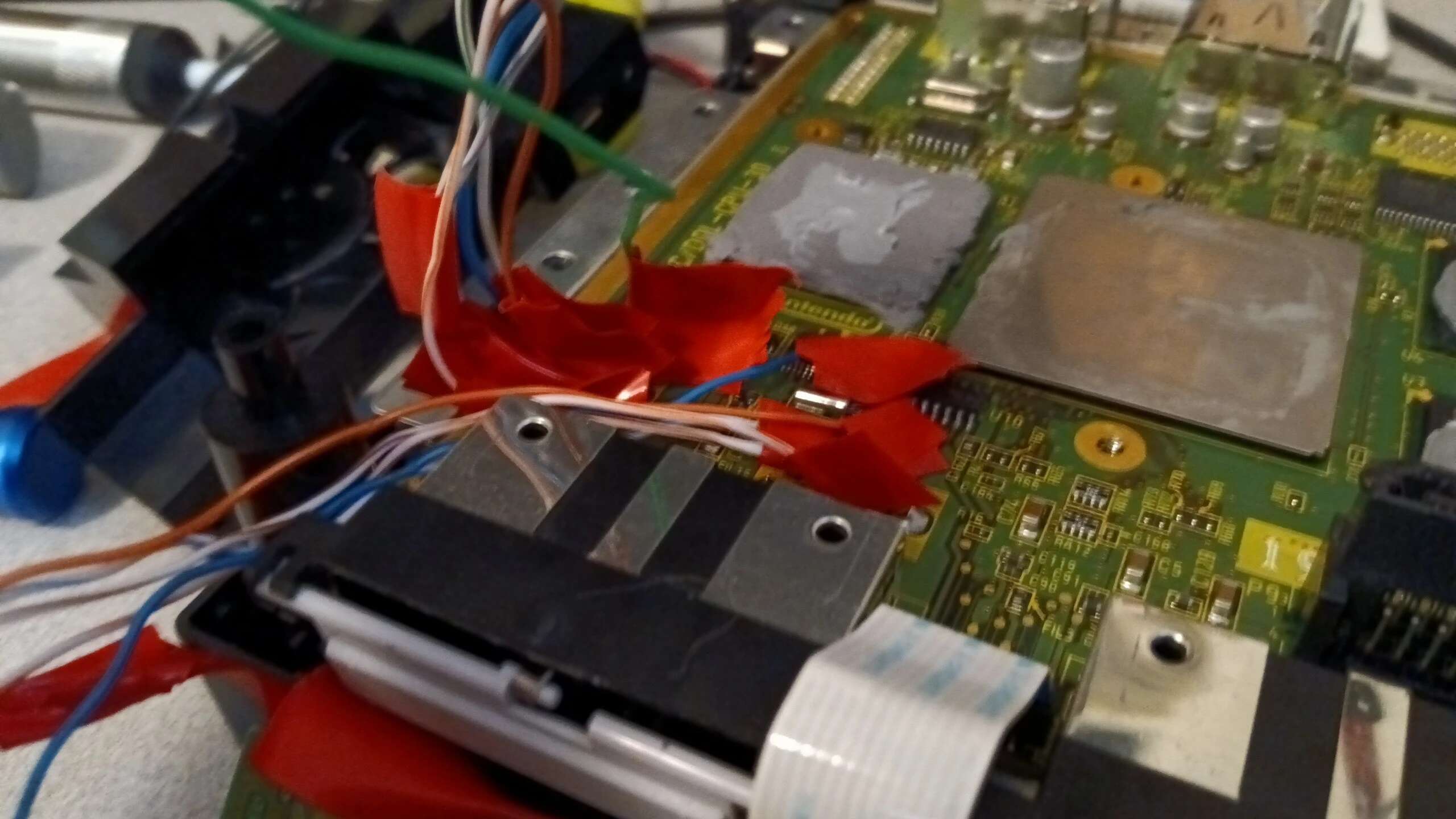
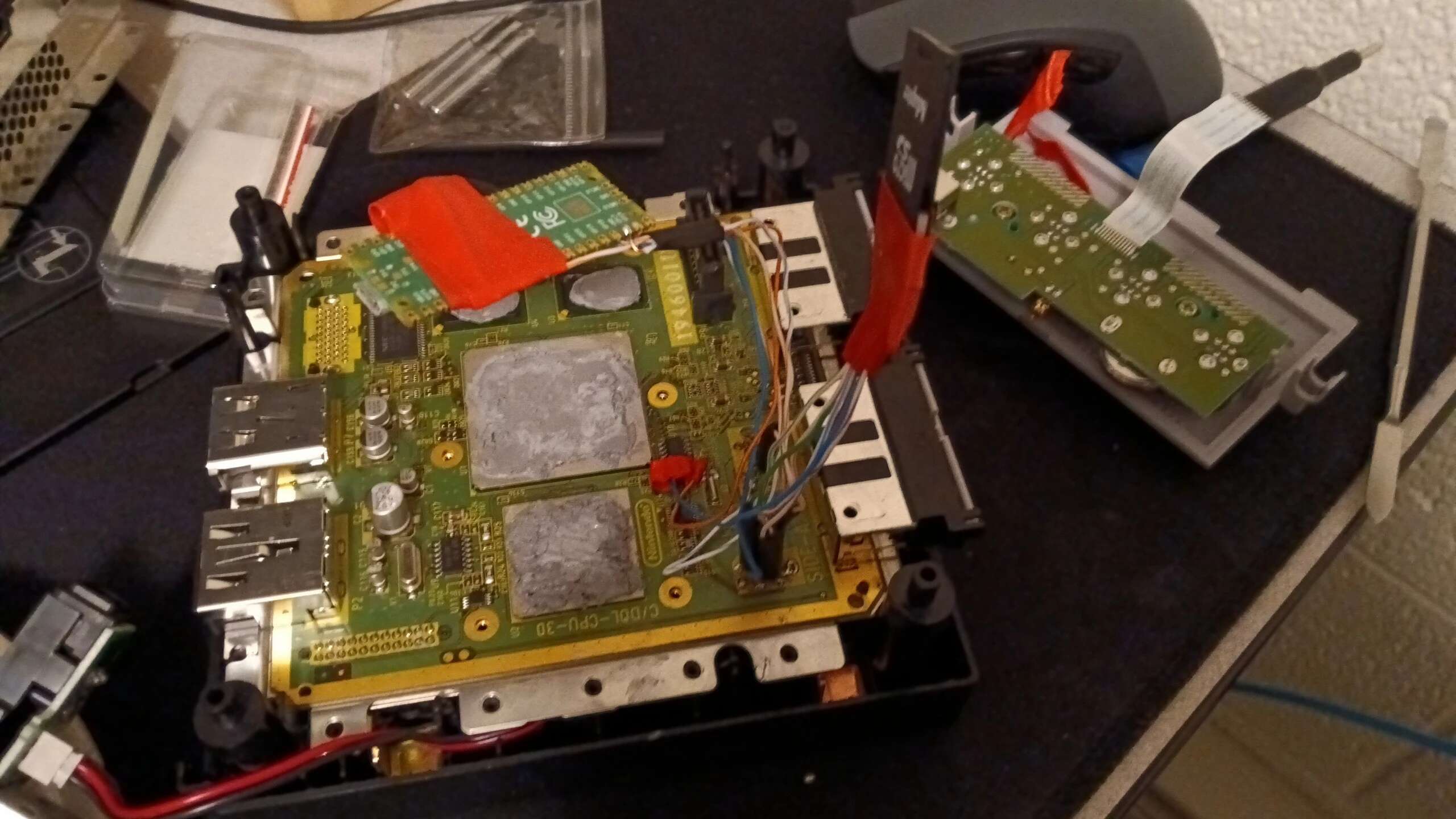
Next, I began wiring. This went along swimmingly. After that, I did some short protection, i.e. I haphazardly wrapped the exposed bits of wire with electrical tape.
Next was figuring out the SD2SP2. I didn’t know the polarity of the capacitor on the SD2SP2 but what I did know was that the source for the board was available on Github. I downloaded the files and opened them in Kicad. This revealed the polarity.
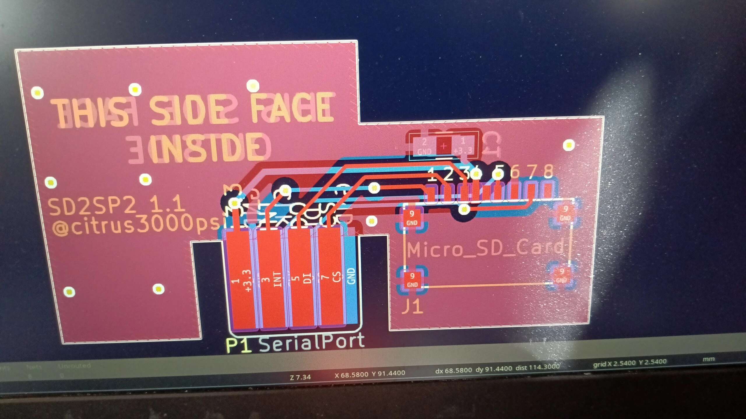
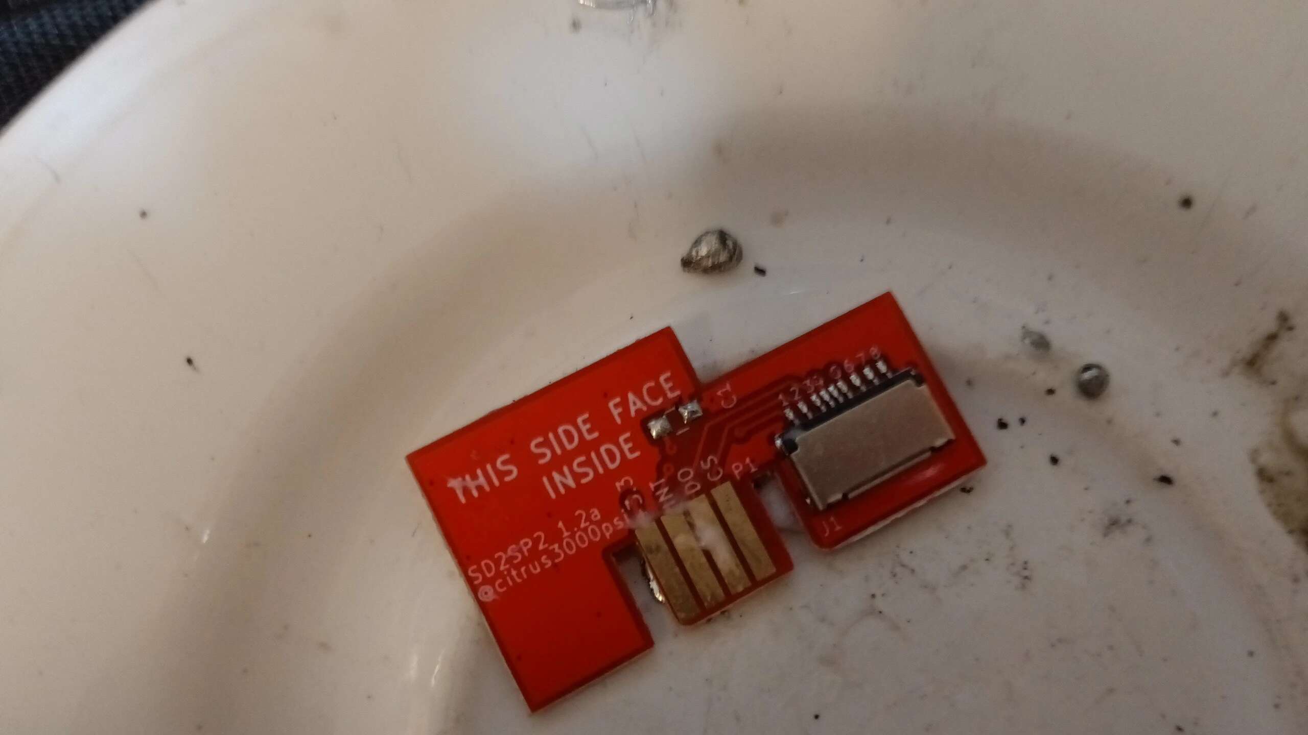
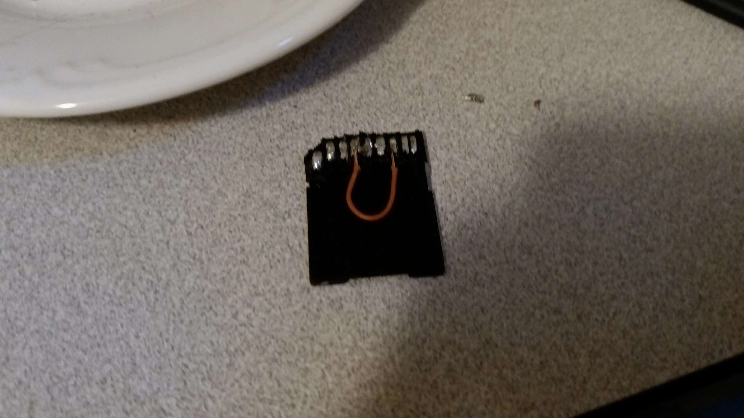
Prepping the SD card was easy enough. 1 wire bridging two of the points, the capacitor in between some other points.
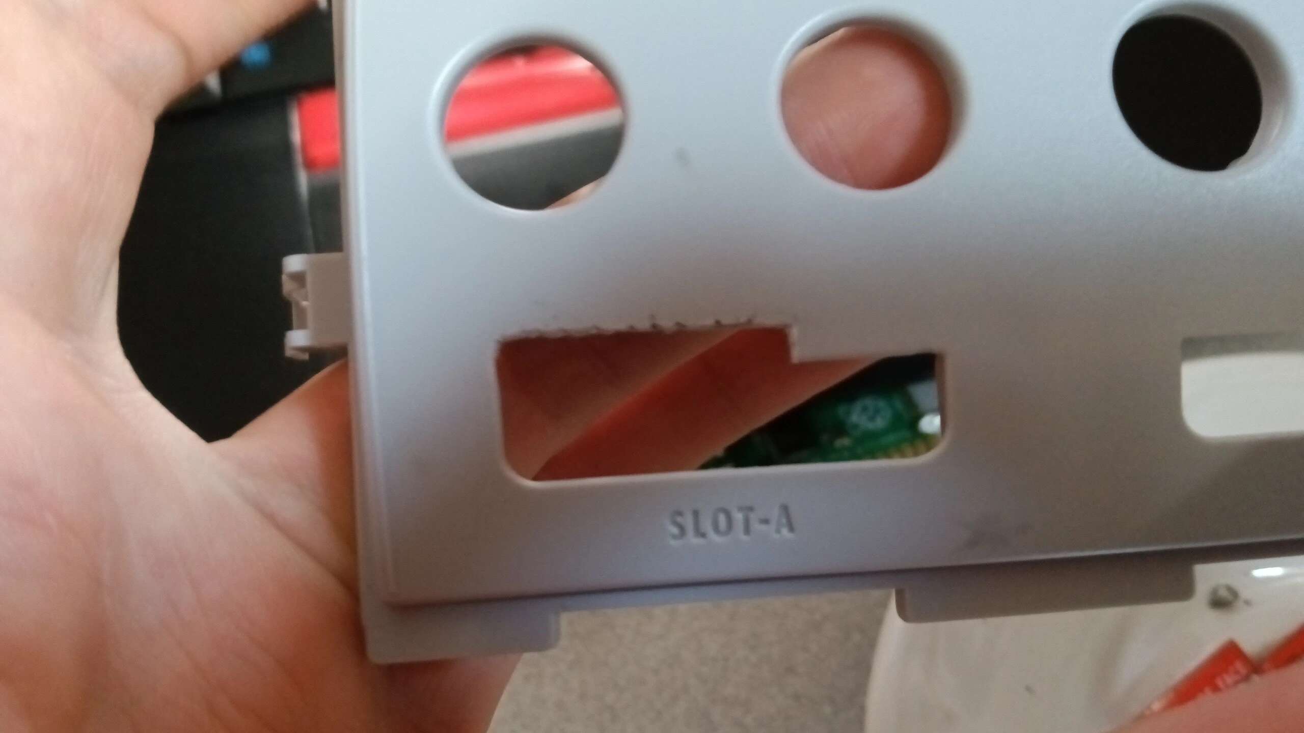
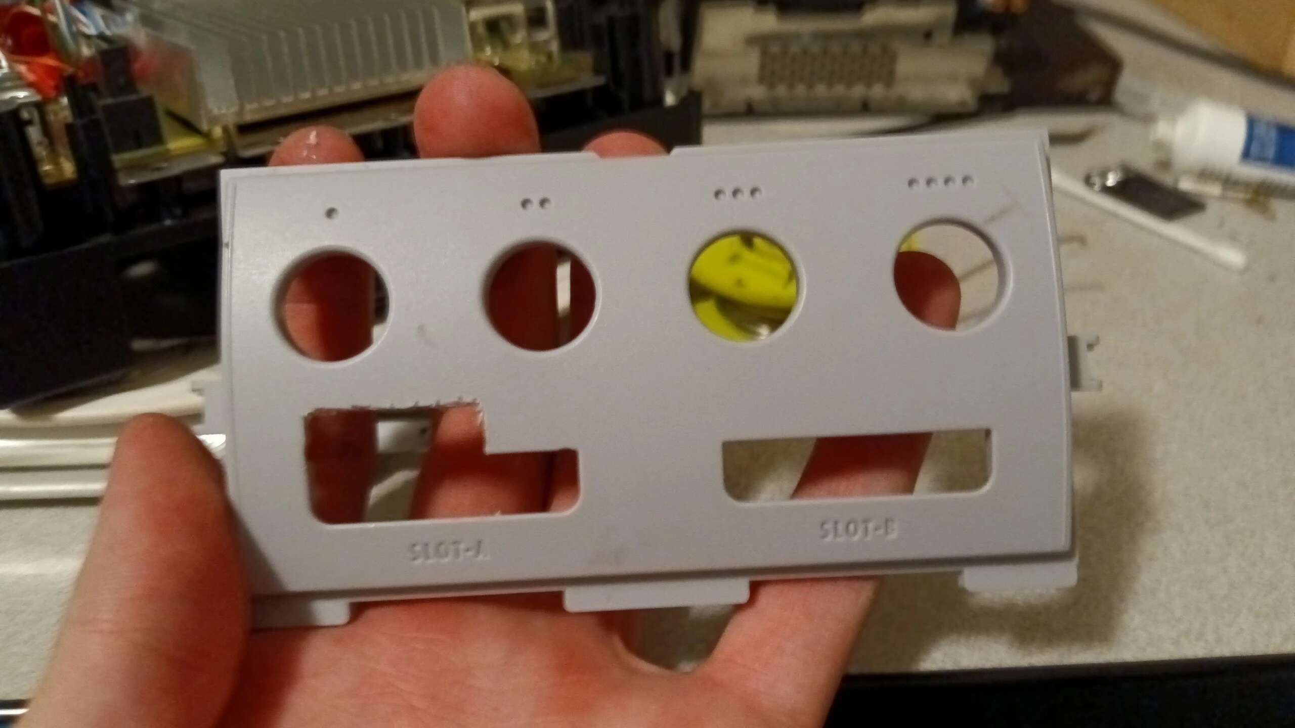
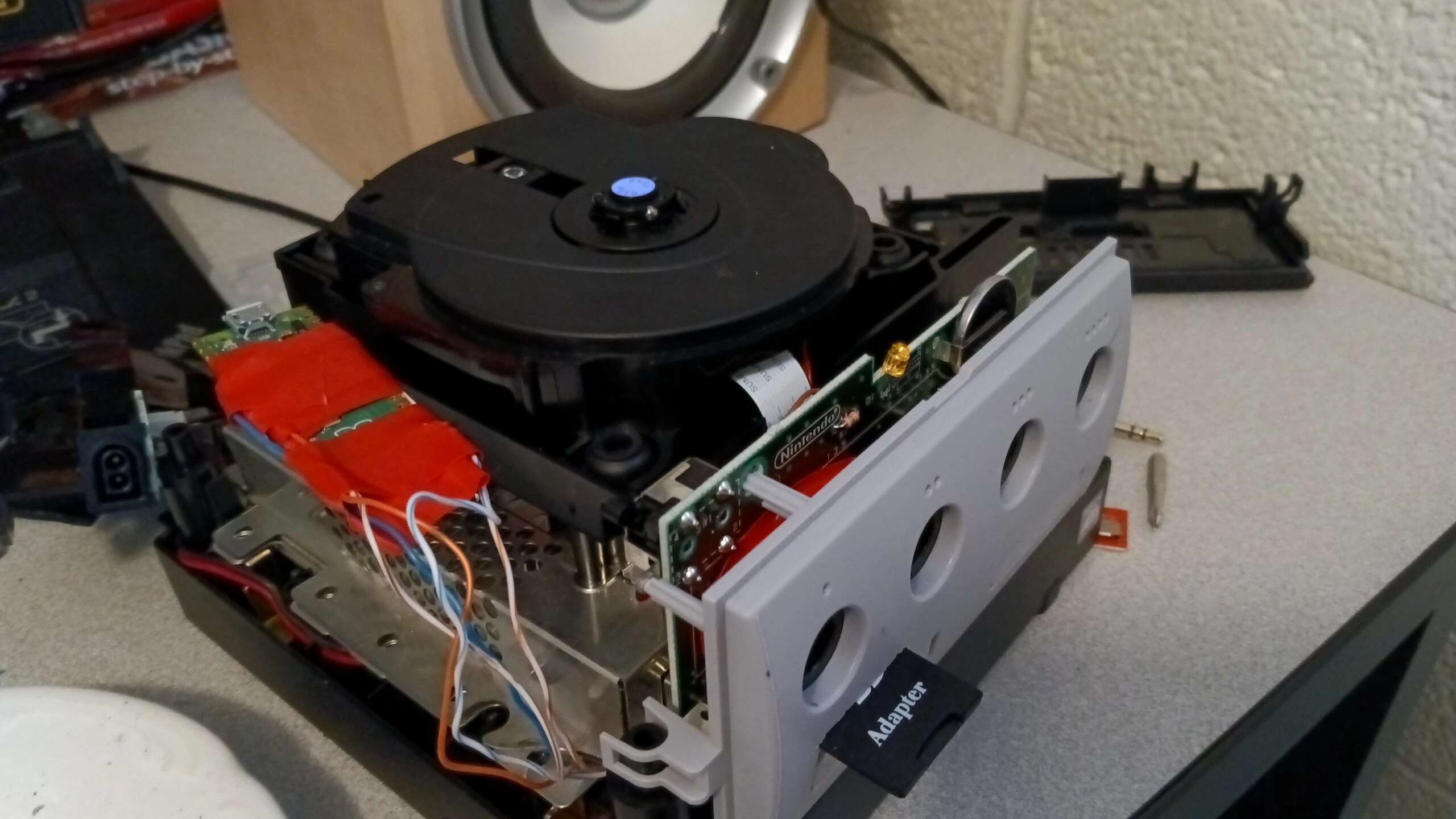
I also needed a way to mount the SD card. After speaking with my roommate, we decided mounting it above the Memory Card 1 slot would be the best option. I used some clippers and a utility knife to cut open a hole and used some electrical tape to secure the SD card. It needed some widening after a test fit.
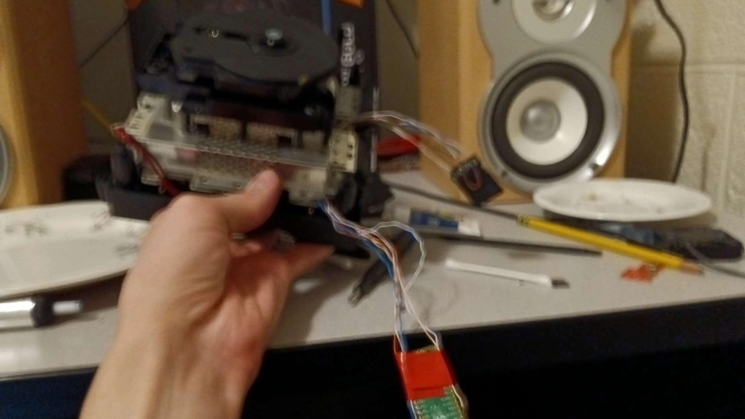
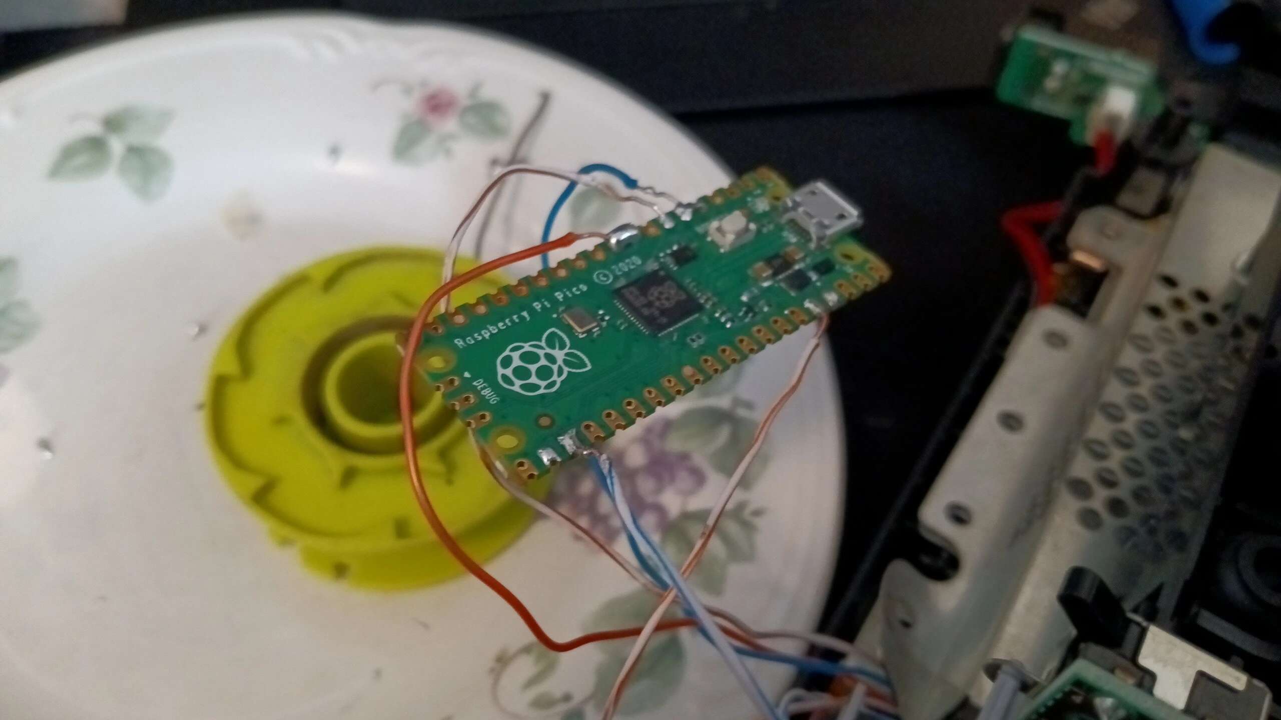
After that, the SD card adapter and the Pico were soldered in. It was far from pretty, but my connections looked OK.
The First Test
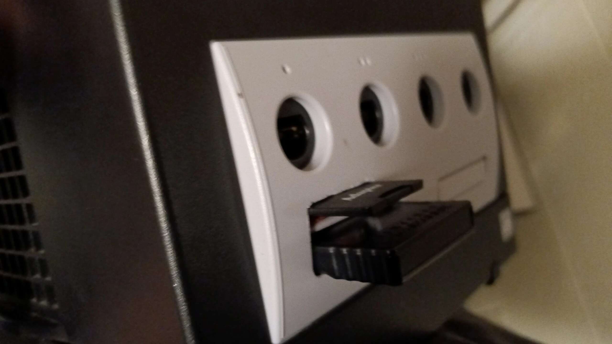
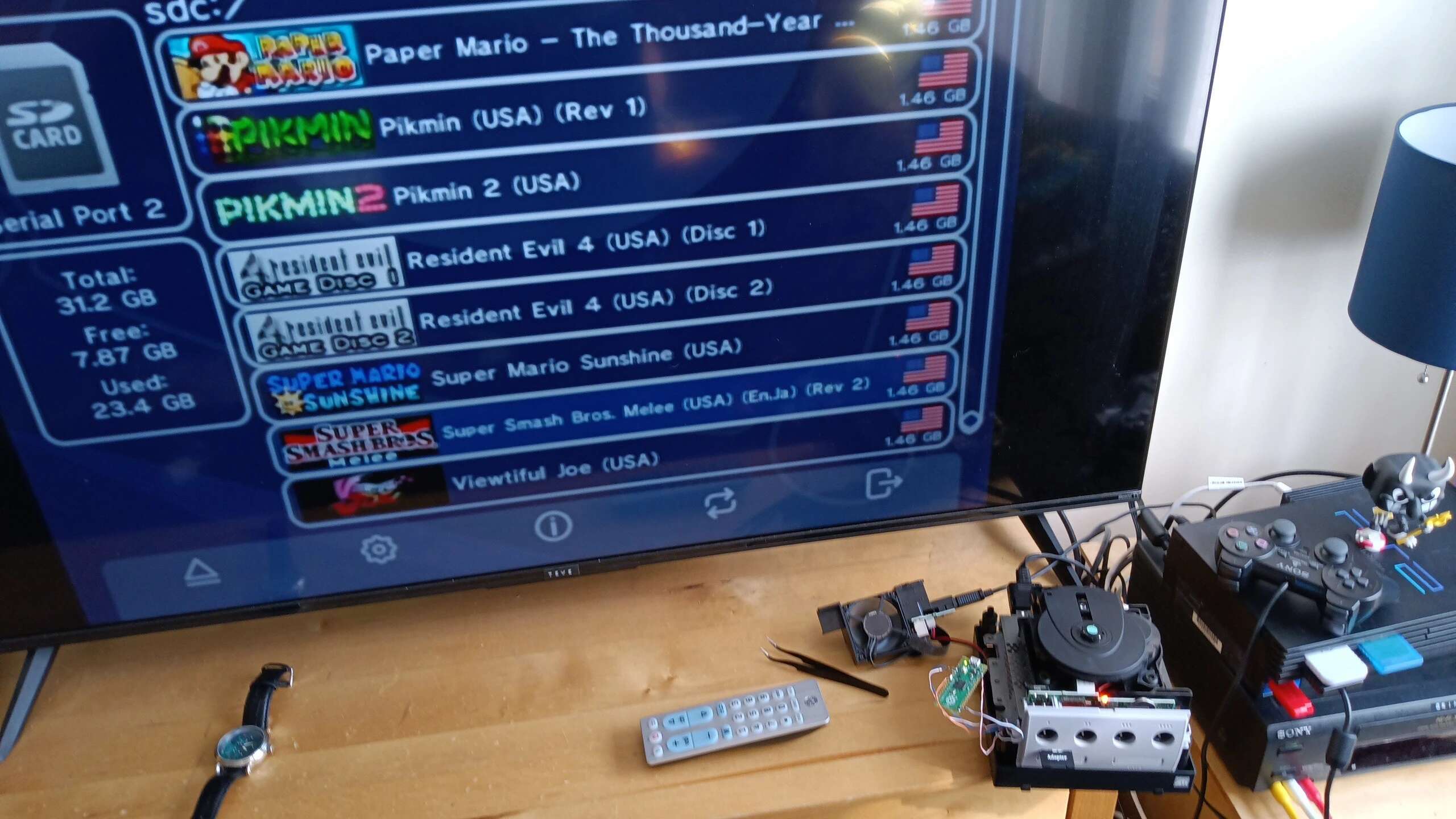
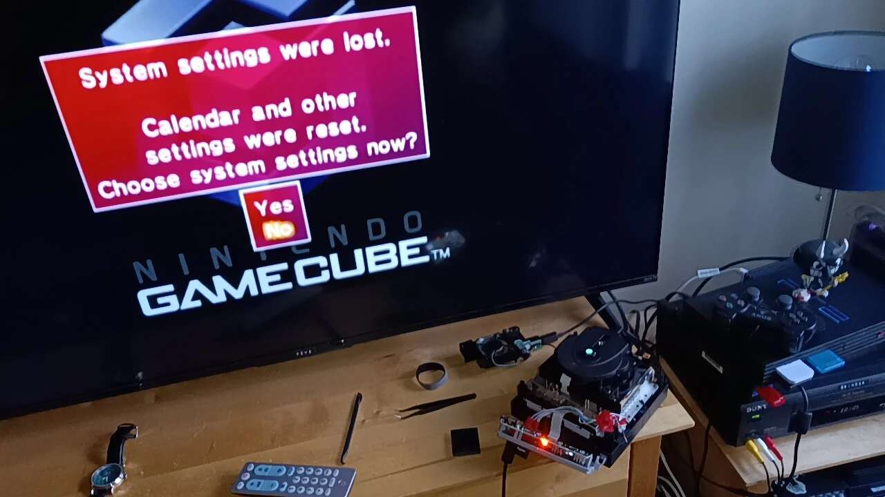
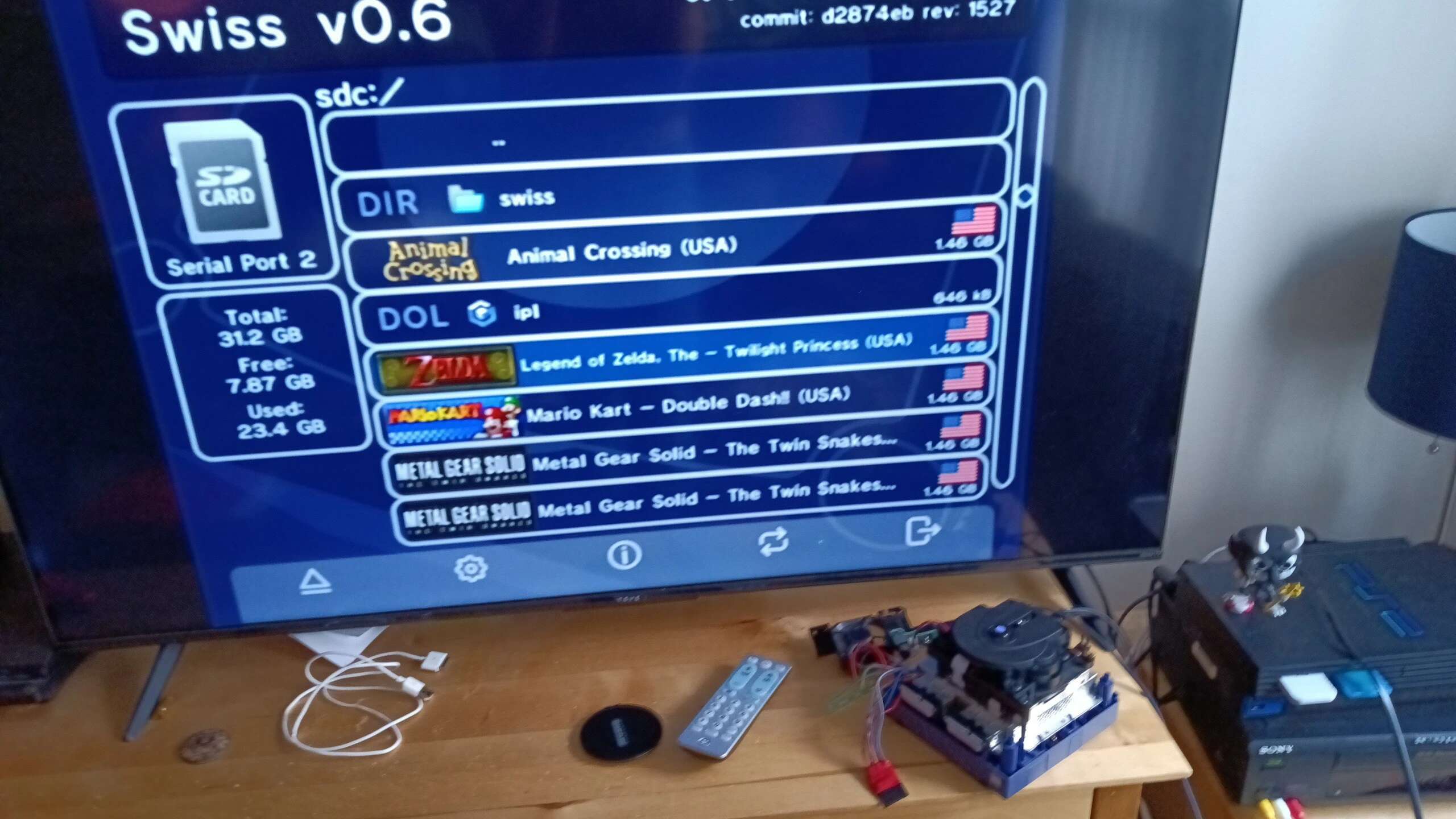
Eager to see the results, I hooked up the GameCube to the TV and turned it on. It worked!
…for about 20 minutes. I wasn’t sure why, but after about 3 on-off cycles in-between games, the console would no longer turn on. It would light up but not give any other signs of life. Thus, I took it apart and began searching for shorts. I couldn’t find out what was wrong! At one point, I removed the Pico. GameCube would then power on. Huh. I tried shortening the wires to the Pico and resoldering. Somewhere in this process, I made a mistake and knocked a capacitor or something off of the Pico that was near the CPU, rendering it cooked. Ugh. Time to order more. I went to DigiKey this time and ordered two Picos.
The Second Attempt
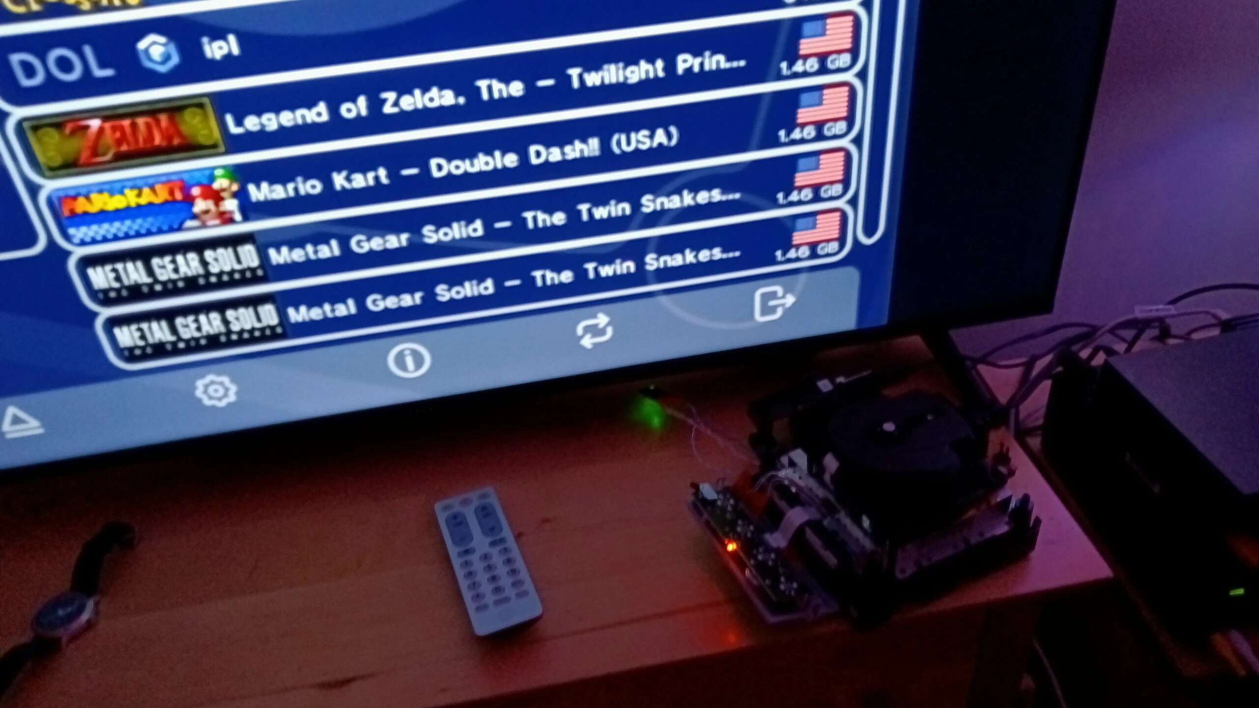
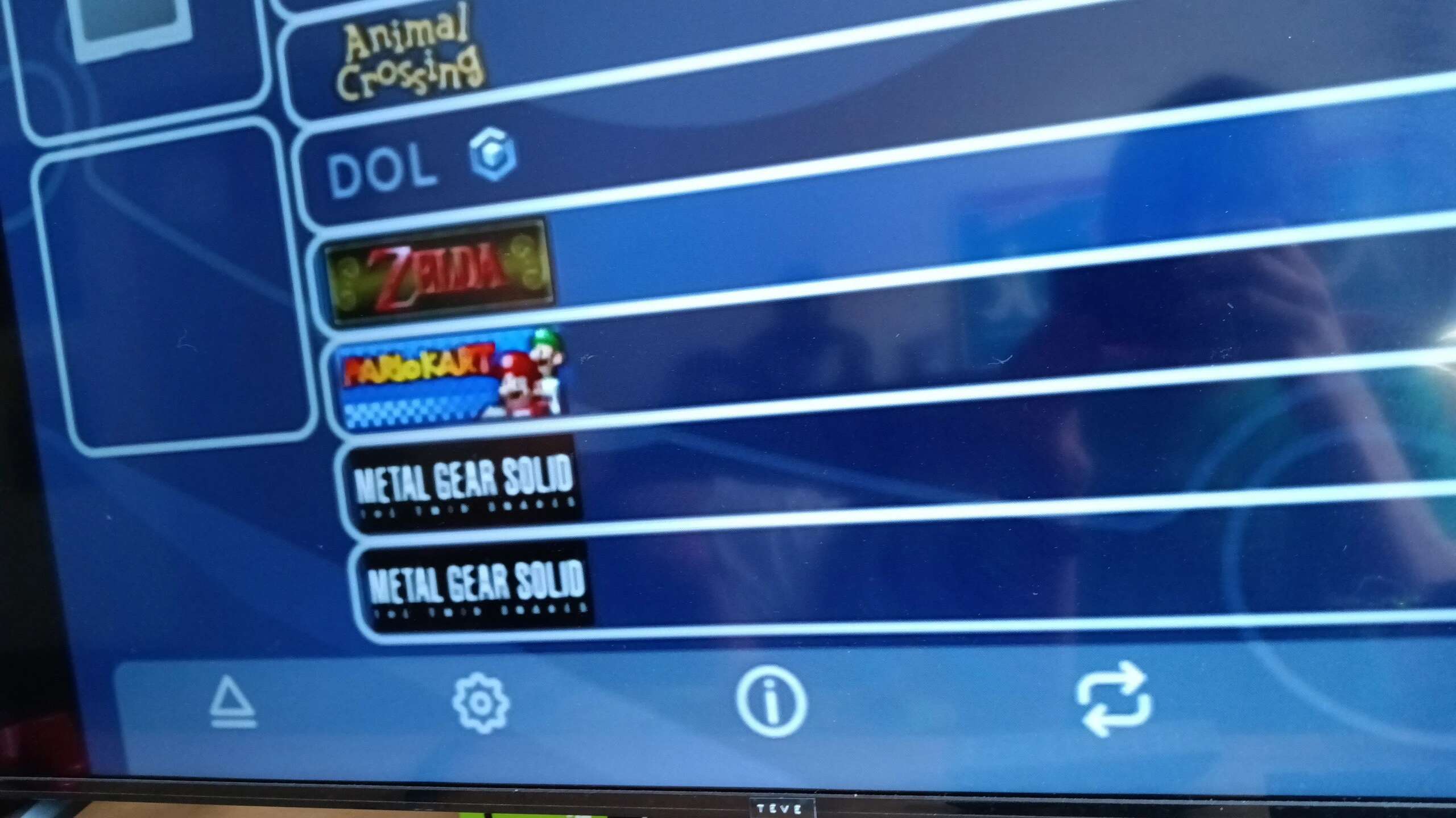
Once the Pico arrived again, I got right back to work. I wired in the new one after programming and yippie! We’re back in Swiss!
…for about 20 minutes. After a few more boots, the text on Swiss started rendering wrong or not at all. Then, it wouldn’t boot again.
Determined to get it working again, I started redoing all of my wiring. I desoldered the wires for SP2 and the Pico and found that the GameCube would still boot with them removed. Fantastic. I started wiring again. At one point I found that my solder wouldn’t stick to my soldering iron any more. I wasn’t sure why. Alas, I persisted. At one point, I was soldering the points that connect to that one surface mounted chip and just wasn’t getting my way. The solder kept blobbing between feet and not joining the way I wanted. I persisted for a while until I made two big mistakes. I knocked off one foot and lifted the pad on another. Fuck. GameCube wouldn’t boot anymore. I ended up facing the music and telling my roommate, who, thankfully, wasn’t mad. I ordered another GameCube, this one listed for parts but with a working board, off of eBay and waited.
Getting Educated
I didn’t take this failure lightly. I wanted to find out why I failed. I’ve come to four conclusions. First, my wires were way too thick. I used 23awg when I should have been using 28awg like the guide states. Second, I wasn’t using kapton tape. My wires weren’t secured in any manner and I found my connections breaking because of stress put on the wires. Three, My short protection was awful. The electrical tape was prone to slipping. I needed a better solution. And four, my soldering iron’s tip wasn’t tinned. I found out that that’s actually something that’s really important when soldering. So, to address these, I did the following:
- Wire Gauge
- I searched all over town for thinner gauge wire but was unable to find any. I had some dupont wires laying about, so I prepared to use those. This probably wasn’t the best solution. I’ll need to order some high gauge wire online in the future.
- Kapton Tape
- This is also something I didn’t address this go-round. SAD!
- Short Protection
- I picked up some heat-shrink tubing to use. This was bigger than my wire thickness, but at least I could put a cut up tube inside of another cut up tube to make something that could shrink around two wires.
- Tip Tinning
- I went to Harbor Freight and picked up a brass wool thing and some tip tinner. I played with it before the new GameCube arrived and it massively improved the soldering experience. My iron was much easier to use in that the solder now stuck to the tips again and the iron seemed to melt solder much faster.
The Third Attempt
At last, the new-to-us GameCube arrived. This thing was FILTHY! I ended up taking it apart and using the ultrasound cleaner at work to get the board cleaned up. The roommate also decided that they wanted their black housing mixed in with some of the purple parts from the new GameCube. I cleaned these parts up real good.
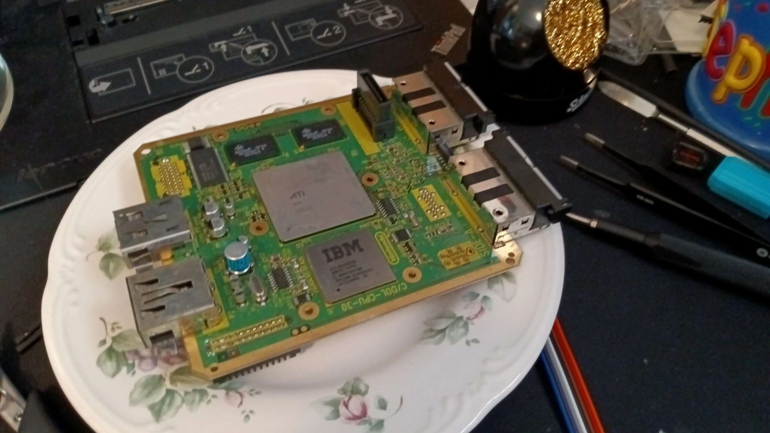
Now it was time to solder. With newly tinned tips and (hopefully) thinner wire, I got to work. I worked more carefully this time in installing the Pico and the SD card. There were no major bumps in the road. I made sure to leave plenty of slack on the wires that connected to the SMD component as I didn’t want to lift another pad and the wires were prone to come loose last time. I used some heat-shrink tubing to anchor them to the more firmly-attached ground connection. I also found that the SP2 wiring went a lot more swimmingly this time. I found I could insert fluxxed wires into the fluxxed holes and then apply solder which resulted in a quick and clean job.
Finally, it was time to see if it worked (again). I hooked it up to the TV and YES! It’s alive (again)!
…and it stayed alive! Fantastic! I buttoned it up and it was still working. Awesome.
Blahajification
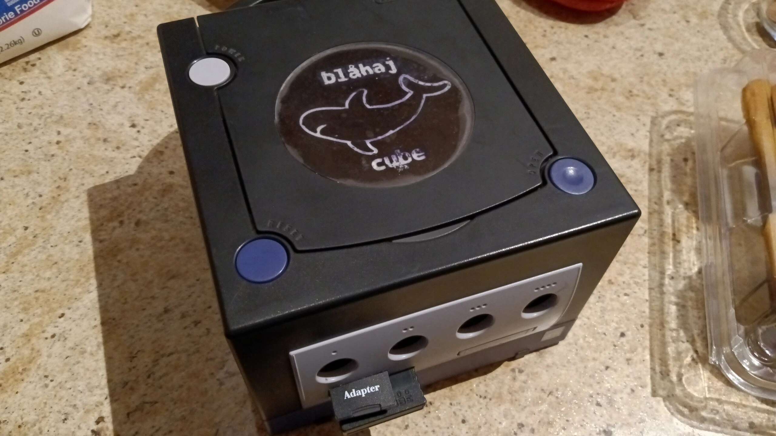
Earlier, while cleaning the housing for the GameCube, I made a discovery: The gem on the disk tray cover is removable! This gave me an idea: What if I made my own gem? I fired up Thingiverse and found a model for a replacement gem5. I printed it and found that there were some inconsistencies in some tolerances, so I fixed those. Next, I embossed a blahaj graphic and the text “Blahaj Cube” into the gem. Using some drywall spackle and some white-out, I filled in this embossed graphic. It wasn’t perfect, but it wasn’t awful either. Finally, I used some see-through glue to attach the acryllic top layer of the old gem to this new insert. There were bubbles in the glue that appered, but hey, sharks live under water, right?
I also found myself dissatisfied with Picoboot launching right into Swiss. That GameCube startup is iconic and I didn’t want it gone. Eventually, I stumbled across cubeboot AKA Flippyboot IPL6, an alternative to the Picoboot firmware that not only shows the GameCube startup before launching into Swiss but also allows you to change the color and the logo of the GameCube. Hooooooh boy. I launched into GIMP and created this:

In Closing
I’m not one for writing conclusions but this project is something that definetley deserves one.
- What was lost
- $40 for a new GameCube board
- $5 plus shipping for a dead Pico
- Countless hours lost to bad soldering
- What was gained
- A better understanding of soldering - The necessity of a tinned tip and what bearing that can have on a project as well as the importance of doing things right the first time to avoid costly mistakes in repetition
- A modded GameCube (duh)
- A chance to do a soldering project / a chance to use a Raspberry Pi Pico
While this was an expensive project in both time and money, I’m quite glad I did it. I learned more about soldering and have something to show for it too, at least until my roommate and I split.